


The Basics of Tires and Wheels
By Scott Whiteman
History: The basic wheel was created around 3500 BC in Mesopotamia and then around 3200 BC they became the building block for Carts and Chariots. The original wheel was constructed by attaching flat boards together in a cross pattern and then cutting the outer edge in a round circle. In the very center a whole was cut out where it was originally placed over a round wooden axle. This of course was of course not the best mechanical design, and they were very heavy and would wear out quickly.
As time progressed lighter and stronger wheel and axle combinations were developed. First finding lighter and stronger woods, next the use of metal hubs and axles, and then in about 1000 BC the development of the wooden spoke wheel.
The next major advancement came in 1802 when the wire spoke wheel was invented. This new design greatly changed wheel assembly, making them very light but still just as strong. This new wheel designed became one of the principal building blocks for bicycles, autos and motorcycles.
Both the wooden and wire spoke wheel were manufactured by hand and with larger demands for the automobile starting in 1910 the all steel disc wheel came into production. The wooden spoked wheel remained in the automotive realm until the late 1920s, at which time it was phased out. However, the wire spoke wheel remains today in the bicycle and motorcycle industry. There were some innovations to the all steel wheel, with stamped center discs in many configurations, some resembling wide spokes.
In the late 1950s alloy wheels were introduced into the automotive world, using aluminum, magnesium and other types of alloys. Because of a fire safety issue with magnesium that material was discontinued. In today's market both the steel and aluminum wheels continue to be the standard.
For today's passenger cars, light trucks and travel/ utility trailers have wheel sizes ranging from 8-inch diameter up to 30-inch diameter, which does not include any commercial trucks or heavy equipment. The most common wheel sized however range from 12- inchesup to 20- inches, with aftermarket wheels going up to 30-inches.
Steel wheels consist of 2 parts, the mounting plate or disc and the rim. Whereas, aluminum wheels can either be a single piece that has been casted or machined or some are also assembled using 2 separate pieces that have been casted or machined.
All wheels are designed with 4 basic dimensions;
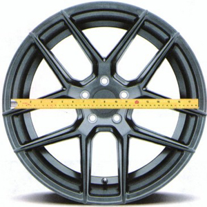
- The wheel Diameter, which is measured from inside the rim area where the tire seats to the rim down to the direct opposite side of the rim where the tire seats to the rim on that side. This dimension is measured in inches, and is the only wheel or tire measurement that is measured worldwide in inches. (see figure #1 for details)
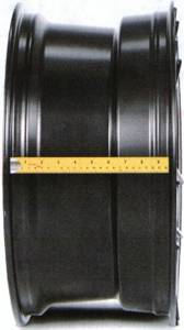
- Next is the wheel Width , which is measured from inside the rim area where the tire seats to the rim directly across to the other side of the rim where the tire seats to the rim.{see figure #2 for details)
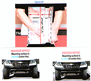
- The third dimension is wheel Offset, which is the area where the wheel disc mounts to the axle (disc/ drum) in relation to both edges of the wheel. A "O" offset would be where the RIM is positioned directly in the center of the mounting point. {see figure #3 for details)
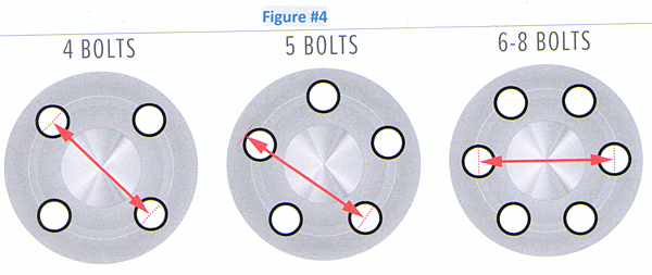
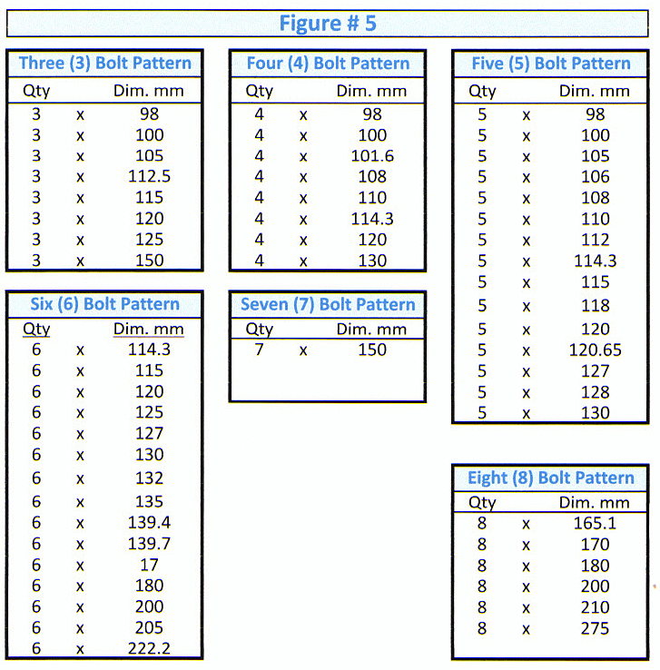
- The fourth dimension is the wheel mounting Bolt Pattern and the number of stud holes or bolts used to fasten the wheel's disc area to the axle hub. This is circular pattern and ranges from 3 bolts to 8 bolts for the passenger car, light truck and trailer. This dimension can be expressed in either inches or millimeters. {see figure #4 for details) & {figure #5 for a list of patterns)
 |
 |
 |
|
 |
|
 |
|
 |
|
Note : 1) There were several French manufactures that used a 3-hole pattern until the early 2000s.
Note: 2) In the early years of automobiles some manufacturers used bolts instead of lug nuts.
Note : 3) Through the 1950s some European manufacturing used a large twist-on center cap to hold each wheel onto the axle instead of multiple bolts/nuts.
The Tire:
As mentioned in the first section the original wheel was all wood with no separate tire. The all wood wheel was a start, but it would wear down quickly and was subject to be easily damaged. So, as the wheel was being developed many ideas were tried to first make the wheel more reliable and then later make it so it would provide a more comfortable ride.
In the beginning an additional strip of wood was tried out, in which they would first boil the wood in water and then bending it around the wooden wheel. This helped but did not solve any of the many problems. So, people then tried cloths and leathers wrapped around the wheel, but this too only provided a little improvement and again wore out very quickly. Then thin/ flat strips of metal were heated and formed around the wooden wheel. This method provided the best result and this concept lasted for hundreds of years.
The metal outer liner provided better reliability, but it did not help with the rough ride you would get riding in a wagon or other types of carriages. Next came types of leaf springs, made from wood first and then metal, which were placed between the axle and the wagon or carriage. This development greatly improved the ride, but still was not perfect.
Then in the early 1800s the pneumatic tire was invented and was patented in 1845. In 1888 John Dunlap further improved the pneumatic tire design and established the Dunlap Tire and Rubber company . The tire has gone through many changes over the years until it has become the tire we know today .
For today's tire all the relevant data and specifications are molded into every tire that is produced. This information can be found on the sidewall of the tire in 3 locations:
- First is the Uniform Tire Quality Grade (UTQG) specification, which is located on the sidewall closest to the tread. This consists of 3 parts; a) the Treadwear, b) the Traction, and c) the Temperature rating of a tire.
- Treadwear - The first numbers are the treadwear grade number, which is a comparative number based on the wear rate of a tire when it is tested under controlled conditions on a specified government test course. For Example: If a tire is graded at " 1 5 0 " , then it would wear one & a-half (1 ½) times longer than the standard tire that is graded at " 1 0 0 " .
- Traction - Next you will see a letter or letters, which are the tractiongrades running from the highest of "A A" , " A" , " B", and to the lowest of " C" . These letters represent a tire's ability to stop on a wet surface as measured under a controlled condition on a specified government test surface of asphalt or concrete. A tire marked " C" may have poor traction performance, whereas a tire marked " A A " has excellent traction.
- Temperature Rating- The third set of data is the temperature grades marked as " A " , " B " and " C", with " A " being the highest rating of a tire's resistance to the generation of heat and it's ab ility to dissipate heat when tested under a controlled condition on a specified indoor laboratory test wheel. Sustained high temperatures can cause the mate rials in a tire to degenerate and reduce the tire life. The " C " rating is the minimum level of performance which any passenger car or light truck tire must meet under the Federal Motor Vehicle Safety Standard No. 109.
- Next in the center of the sidewall you will find the tire's construction information:
- This usually starting with the Manufacturer's Name and across from that the Make or Model of the tire. An example of this wou ld be "Cooper" (Coper Tire company)and "Evolution" ( the tire modelname).
- Next you will find a sequence of Numbers and Letters, starting with a letter. This is the tire Classification, where; a) P is for Passenger car tires, b) LT is for Light Trucks, ST is for light utility and travel trailers, and d) MC is for Motorcycles.
- Then you will see 3 numbers that designate the tire's Width. This dimension is measured from the outer sidewall to outer sidewall, at the widest point. These numbers are expressed in millimeters (mm). An example of this would be the numbers "225", which indicates that the tire's width is 225 mm.The next 2 numbersare the Percentage (% ) of the tire's Height to the tire' s Width. An example of this would be the numbers "225/60", which means that the tire height is 60% of the 225 mm tire's width. (Note : There is no actual height number, on the percentage)
- Next on the tire is the type of Construction using a letter. Basically, there are only L Lypes or amomo t1ve, 11gh1: uuck, uaiier and motorcycie tire construction and they are the Bias Ply tire and the Radial Ply tire. In today's market over 95% of all tires are the Radial type tires . This means tires today will be marked either with an " R " for radial or a " B " for the bias type tires.
- The next 2 numbersare for the wheel/ tire Diameterm. This number can range from 6-inches"6" all the way up to 30 inches "30" for wheels/ tires that fit onto passenger cars or light trucks. An example of this would be "225/60Rl 5", where the last 2 numbers indicate that this tire fits onto a 15-inch diameter rim.
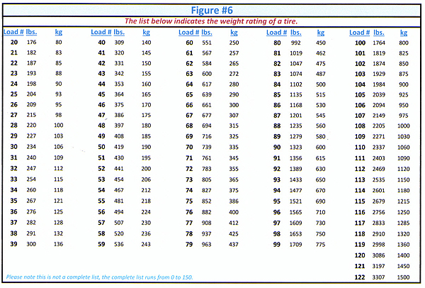
- Followingall of the tire size information there is a 2-digit number indicatingthe tire's Load Index/ Range. These numbers indicatethe safe load rating each tire has when tested in a controlled government environment. (seefigure#6fordetails)
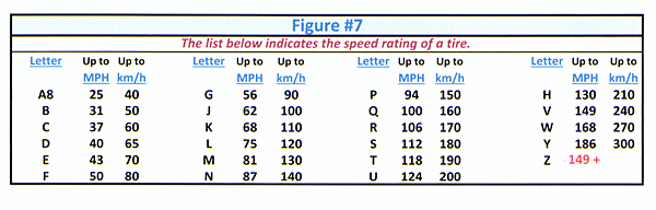
- Lastly in this sequence of numbers and letters is the tire's Speed index. This letter indicates the maximum safe speed a tire can handle during a controlled test at a government test facility. (see figure #7 for details)
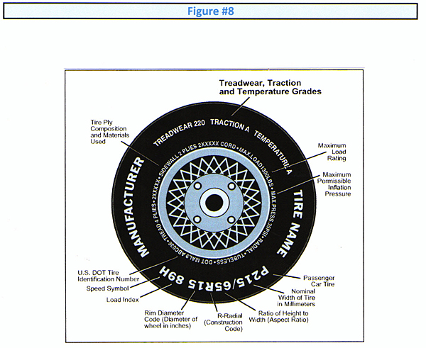
- Finally, the last area on a tire that contains pertinent data is also located on the sidewall next to the bead of the tire where it seats to the rim, and there is a group of 8 different pieces of data.
 |
- The first piece of information is the U.S. Department of Transportation (DOT) Tire Identification number. This is a number each tire manufacturer must apply to a tire provided to them by the DOT, and is the file number for their manufacturing processes, raw materia ls used, and the constructionof each series of tires. For the average consumer this number is not important when purchasing a tire, but it could become important if there is a tire failure.
- Next listed on most tires are the actual Tire Construction, indicating both the numberof sidewall laye rs and the number of tread layers. An example of thiswould be 2 layers sidewall/ 4 layers tread.
- After this information you see the Maximum Load rating, usually this number is listed in pounds. This number will also correspond with the Load Index number listed on the cen ter of the sidewall. An example wou ld be MAX LOAD 1200 LBS.
- The next piece of data is the Maximum Inflation Pressure, which is typically listed as MAX PSI . An example of this would be MAX PSI 35 lbs.
- Then the following 4 numbers are for the Date of Manufacturer, with the first 2 digits being for the week of manufacture and the last 2 are tor the year . An exampie of this would be " 2020", which indicatest he tire was manufactured during the 20th week in the year L0 20.
- In addition, some tires are only designed to be assembled and driven in ONE direction, so these tires also have an Arrow placed on the tire indicating the Direction of travel.
- Some types of tires may have a Triangle A. or a TWI marking placed on the side of the tire, close to the tread, indicating where the Tread Ware indicator is located.
- Lastly some special tires (i.e. for motorcycles) are marked Front or Rear, indicating that they should only be mounted on the front of rear. (see figure #B for location of all data)
 |
